Development of custom electronic boards with CNC Router.
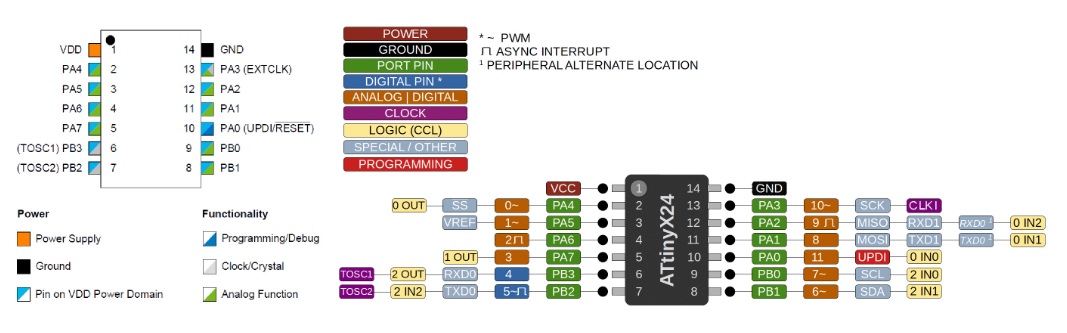
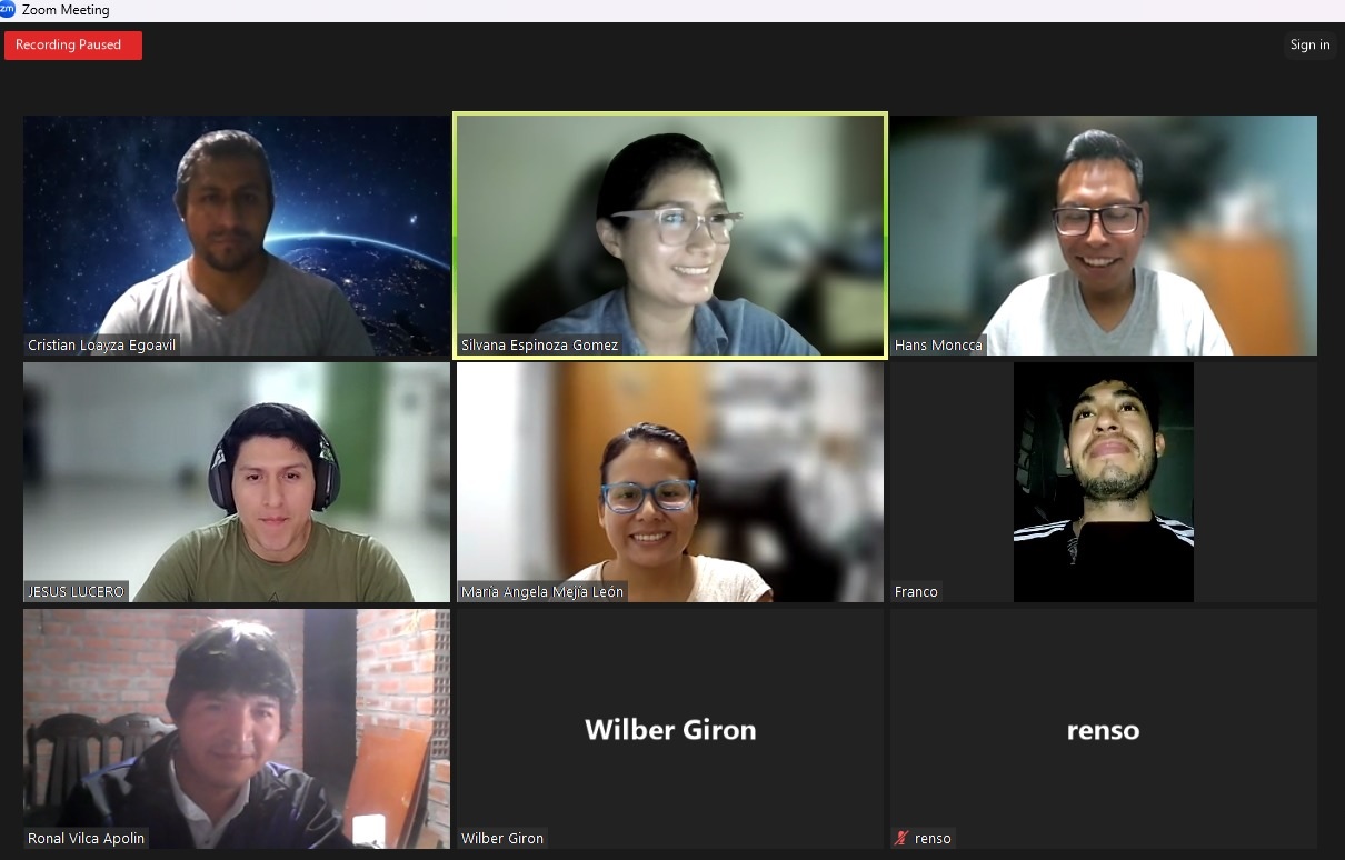
During this week 6 of group work, we met with the Fablab Perú team, based in Lima, while I participated from Huánuco. Our objective was to conduct discussions and comparisons on the microcontrollers selected for our study. Each of us dedicated ourselves to the detailed analysis of a specific microcontroller, in my case I was talking about the Attiny1624 AVR, then presenting our findings to our classmates.
I decided to study this microcontroller from the AVR family because, despite its very small size, it offers a wide range of features. I plan to deepen its knowledge by consulting its data sheet and exploring its various functionalities in greater detail.

The experience I have had this week working as a team has been extraordinary. We have learned a lot thanks to our joint collaboration. Each of us dedicated ourselves to studying the data sheet of the assigned microcontroller and subsequently shared our conclusions about the advantages of these devices. This process allowed us to acquire knowledge quickly and efficiently. Without a doubt, teamwork has been key to this success.
Although I didn't have the opportunity to work directly with the Attiny1624, its potential for special applications is truly impressive. Likewise, the other microcontrollers I mentioned above are also very promising. In fact, I have already placed an order to purchase them and thus expand my personal inventory. I'm looking forward to putting everything we've learned into practice and exploring the functionalities detailed in their data sheets.
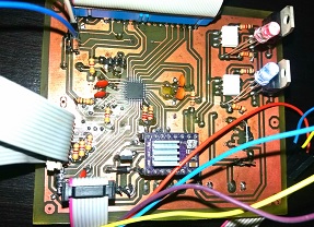
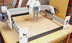
For my individual task, I designed a board for the Xiao electronic card compatible with the ESP-C3 and RP2040. I developed this board using my homemade CNC, which I introduced during week 4. My goal was to explore new functionality while making progress on my final project. This experience allowed me to put my design and manufacturing skills into practice, while also contributing to the progress of my ongoing project.
For the design of my electronic board, I chose to use Eagle software. The steps I followed were as follows: first, I opened a new project and then 'Schematic'. This allowed me to start the design process in an organized and structured way using the tools provided by EAGLE .
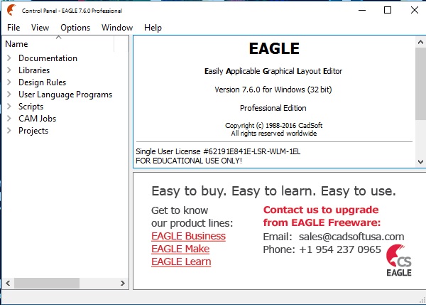
New project.
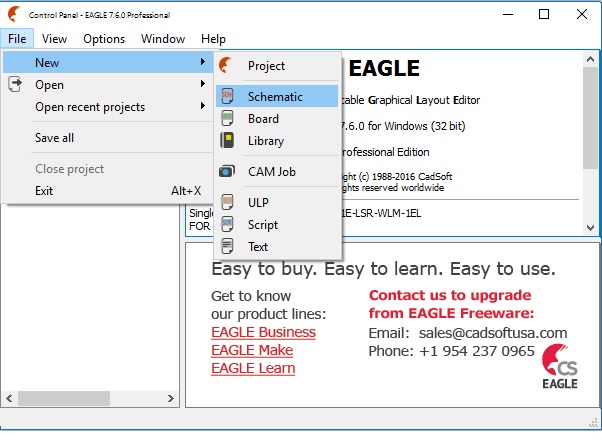
New Schematic.
Once on the blank page of the Eagle software, I started by adding the necessary components, such as the XIAO ESP32-C3, and proceeded to to import the corresponding libraries. Teamwork was of great help in this process, since it allowed us to learn more about the characteristics and advantages of these components. This was essential for the development of the electronic board as my final project required it, allowing me to customize the inputs and outputs according to the specific needs of the project.
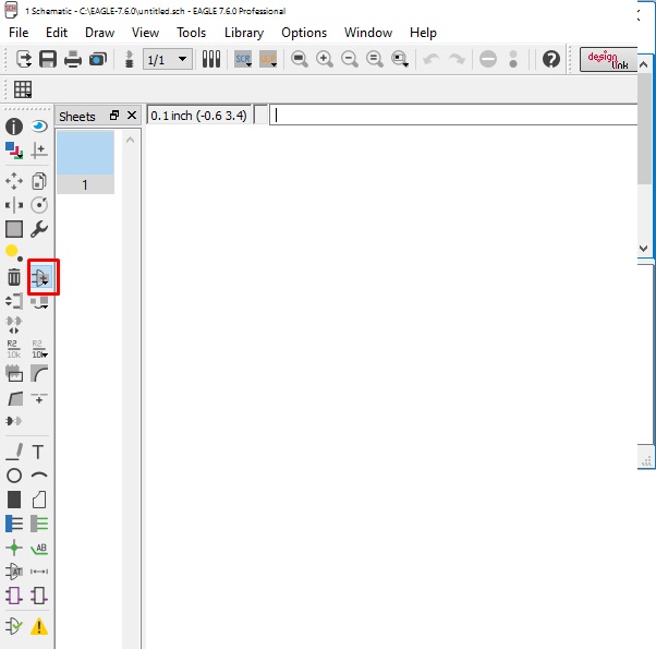
Add component.
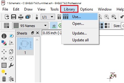
Place Adding libraries.
In the Eagle software toolbar, we proceeded to add components, selecting the XIAO ESP32-C3 card model to import it. Once imported, we chose the pins we needed to configure and then assigned the corresponding names to those pins. This process allowed us to prepare the electronic board to adapt it to the specific needs of our project.
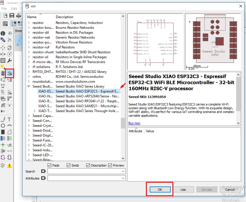
Importing to XIAO ESP32-C3.
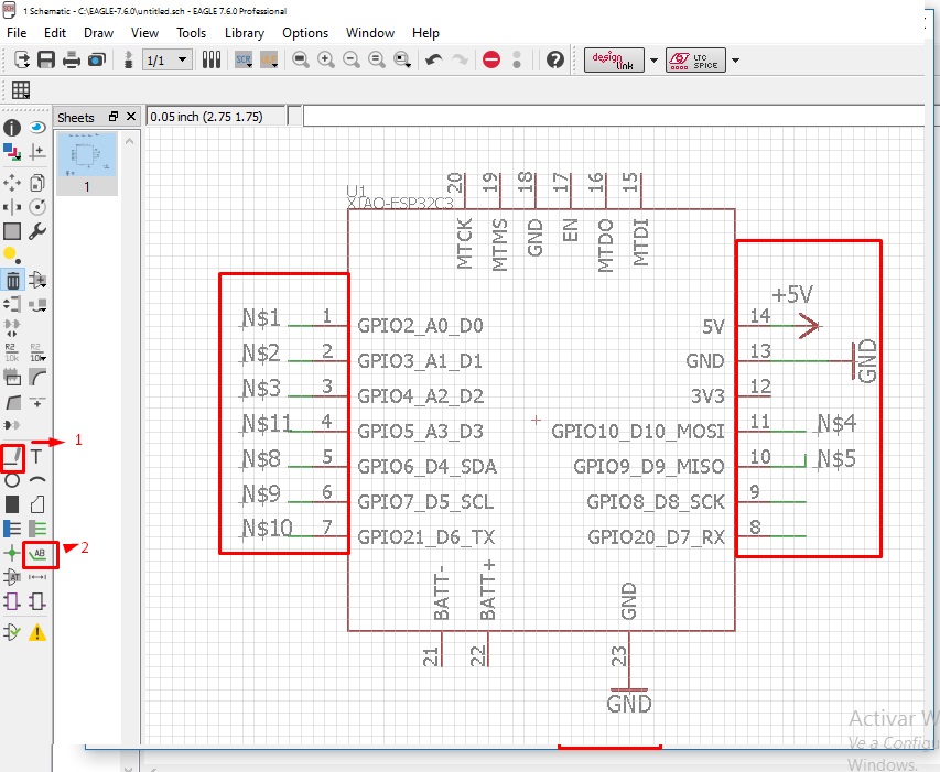
XIAO pin recognition.
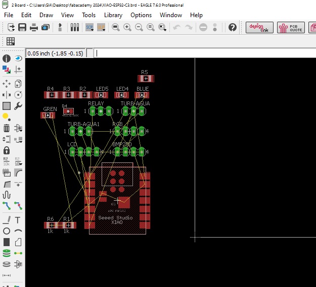
I then proceeded to change the names based on the information provided in the XIAO ESP32-C3 datasheet. Later, I added the connectors and other necessary components following the same naming process. Finally, I completed the electronic board, as shown in the attached image.
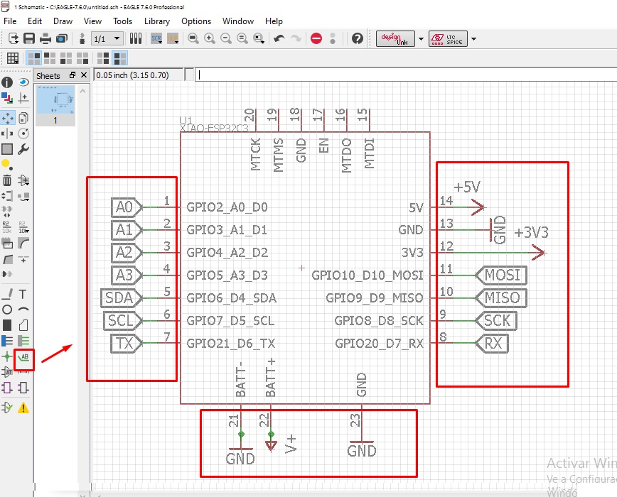
Configuring the names of the XIAO ESP32-C3.
Board layout and final components.
Once the connections of each component with the XIAO ESP32-C3 were completed, we proceeded to route and distribute the electronic components on the board. At this point, we were asked to save the project and subsequently a new window was opened where we organized the components in an orderly manner to facilitate the process of designing and manufacturing the board.
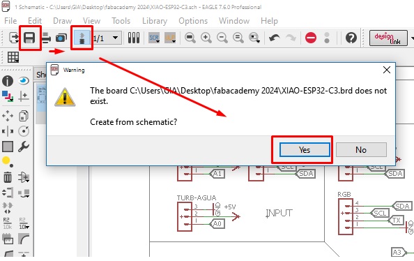
Component distribution.
Component routing and ordering window.
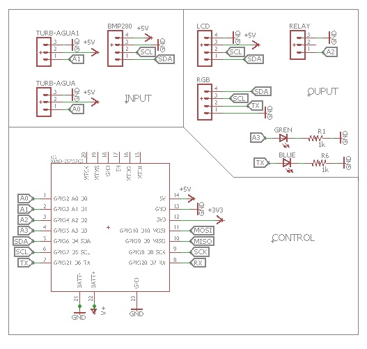
We make a proper layout of all the components inserted into the board, designing it in a way that it serves as a versatile testing platform. We incorporate an OLED LCD, three analog sensors, an RGB module and a BMP280 sensor. The result is shown in the attached image. However, we are aware that this design can be further optimized for future iterations, as a version ("V2"), better adapting it to the specific needs of our final project.
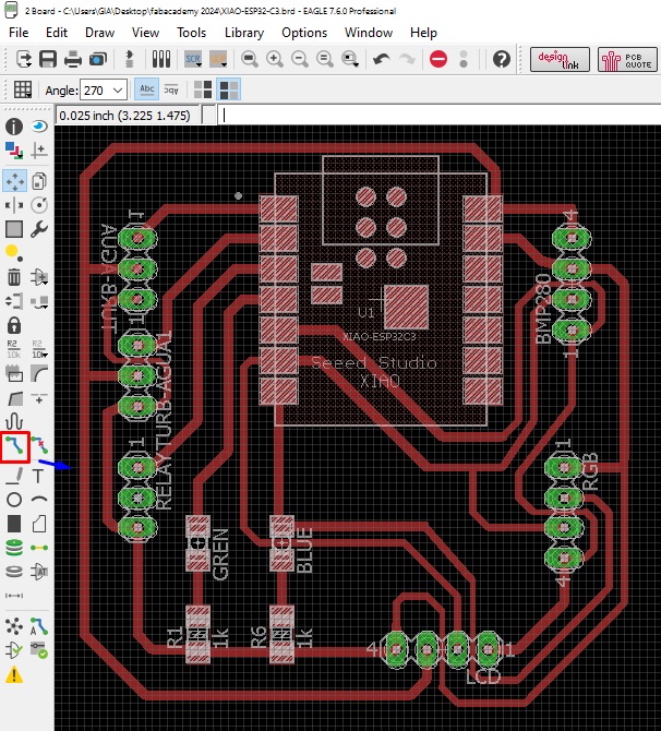
End plate to produce.
Once the design is complete, the next step is manufacturing the board. To do this, we resorted to the step-by-step process we learned during week 4. We used Flatcam to carry out the necessary processing, making sure to adjust the parameters according to the specifications of our manufacturing machine.
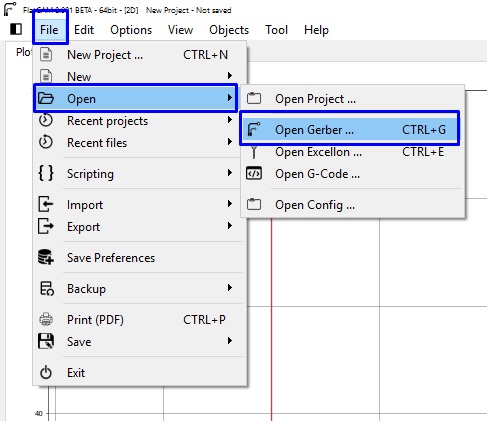
Import gerber made.
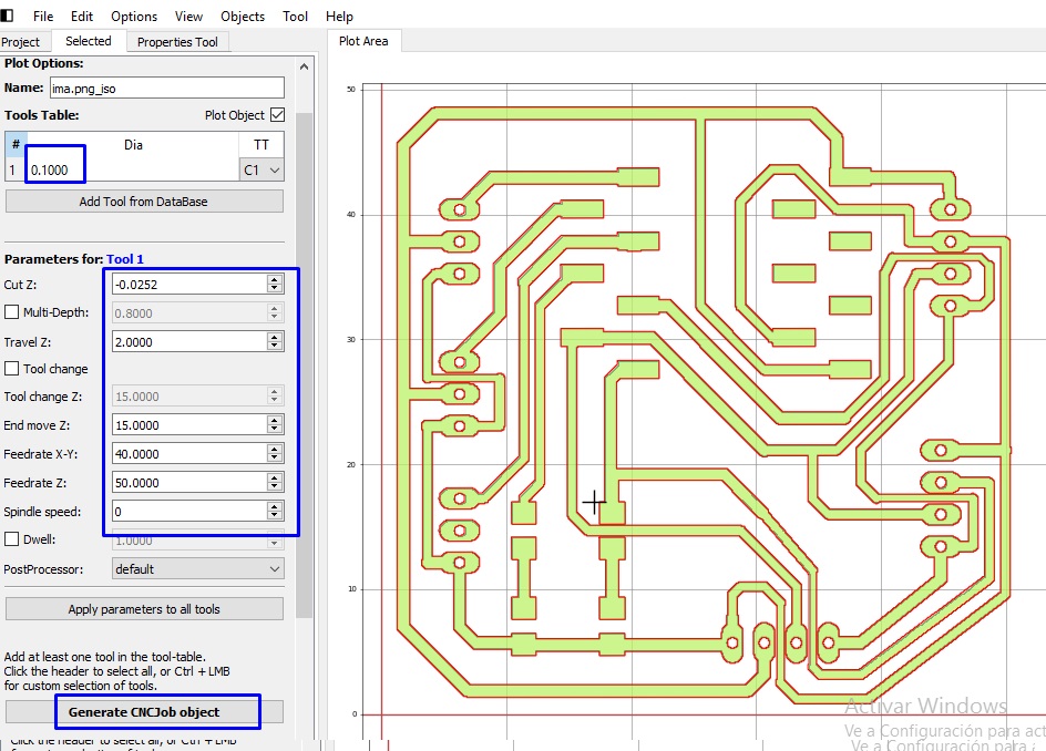
Set the parameters according to the machine.
The next step is to generate the G-code files for production using the electronic board CNC.
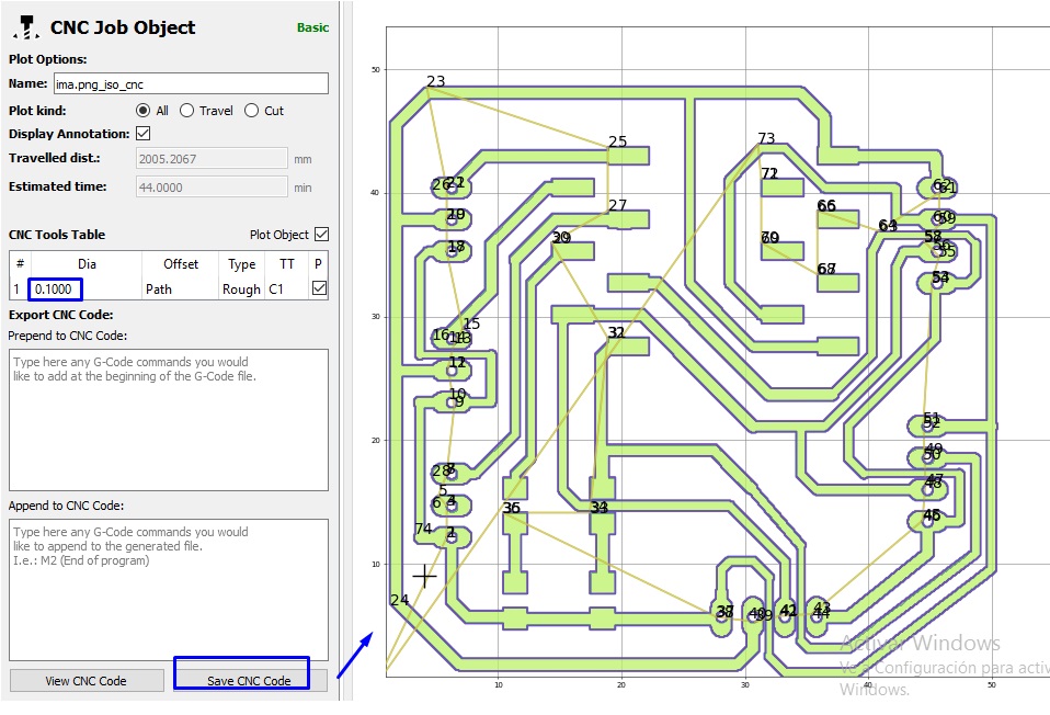
Gcode generation rotation.
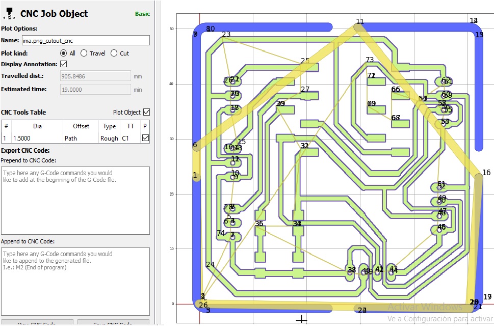
Gcode generation cut.
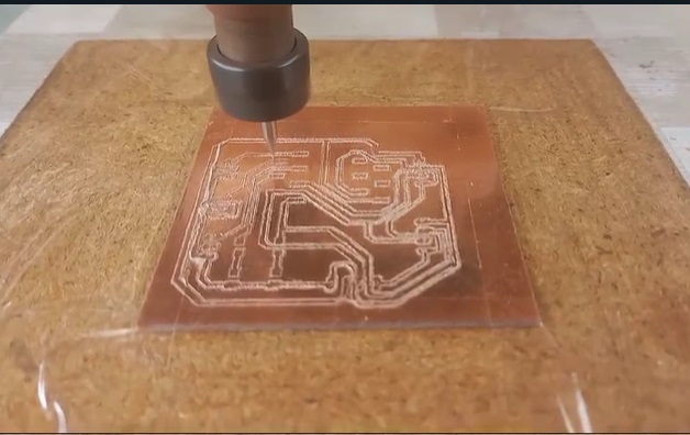
Routing the board.
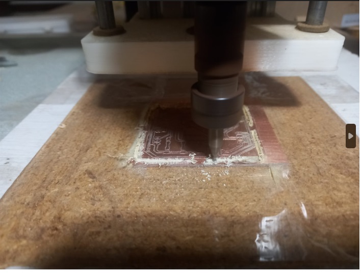
Plate cutting.
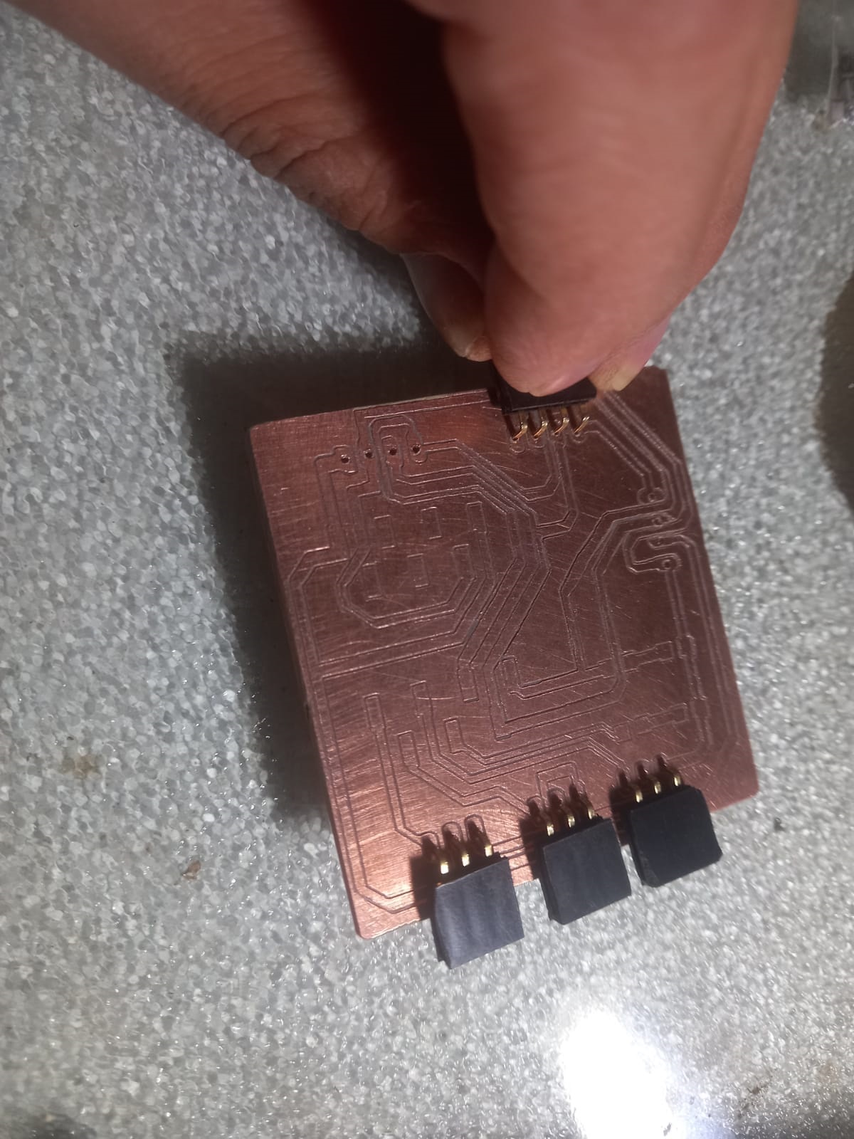
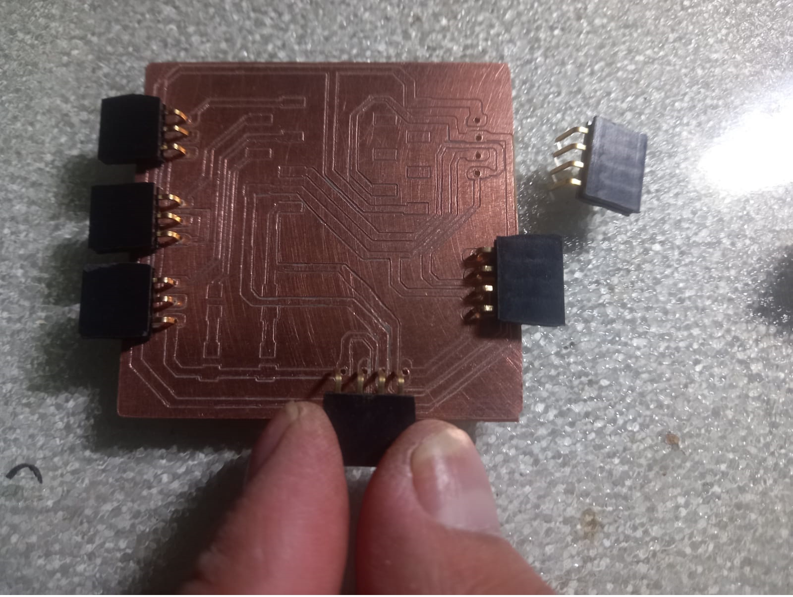
Placing the components.
.
For this task, we will carry out the installation and selection of the XIAO RP2040, in order to program a set of instructions that fits our specific needs.
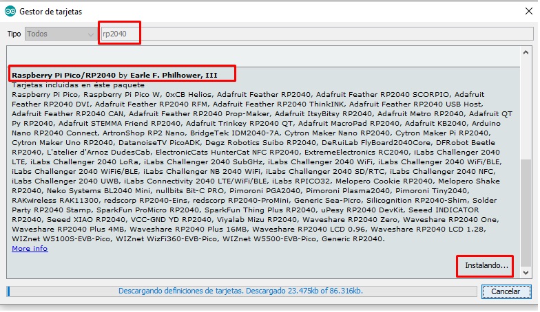
Installing the driver.
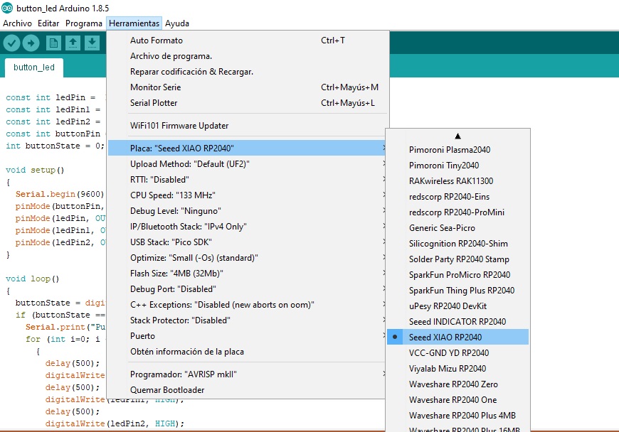
Selecting the electronic board.
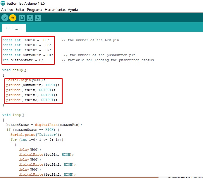
The next step is to program the previously developed board, which has three soldered LEDs and a button or pushbutton that we can use as input, while the LEDs act as output.
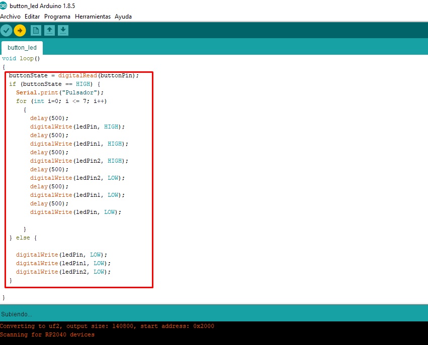
After entering the code and declaring the variables, we move on to configure them in the corresponding settings section. Once configured, we proceed to implement the light sequence.
.
You can see the play of lights generated by the preconfigured LEDs on the control board. These strategically arranged LEDs offer a dynamic and captivating display that complements the system's functionality.
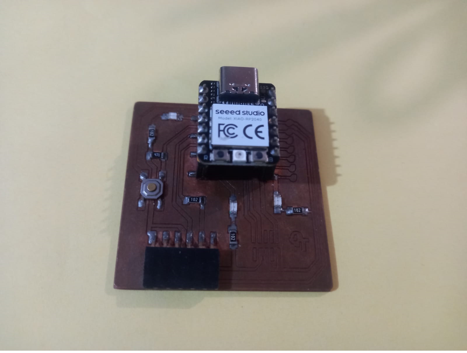
LED control board.
I also performed another test shown in the example below: testing an OLED LCD. I carried out this evaluation using a control board designed specifically to meet my needs.
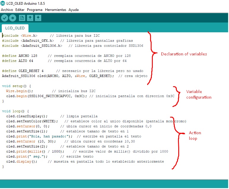
Variable configuration OLED.
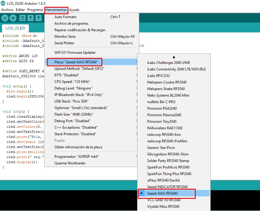
Selection of RP2040 electronic board.
We loaded the program using the Arduino IDE and you can see its progress in the images below.
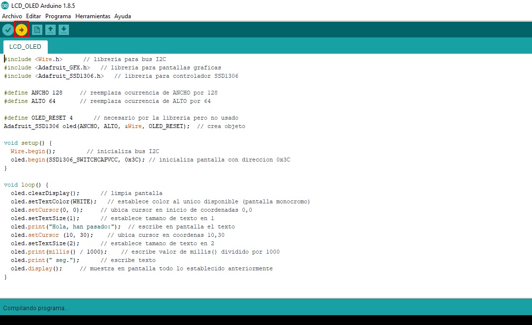
Variable configuration OLED.
Selection of RP2040 electronic board.
Finally, I present the tests carried out on the board with the XIAO RP2040. The performance and capabilities of this controller are truly impressive.
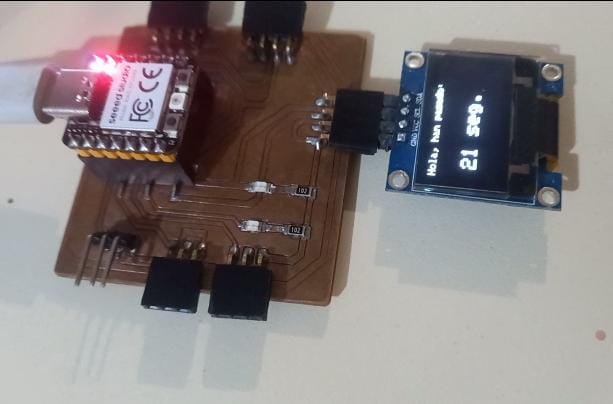
Oled LCD.
OLED LCD control.
You can improve this: Finally, I tested a water quality sensor using the TDS sensor, an OLED LCD and the XIAO ESP32-C3, I carry out these tests since my final project is related to this specific topic
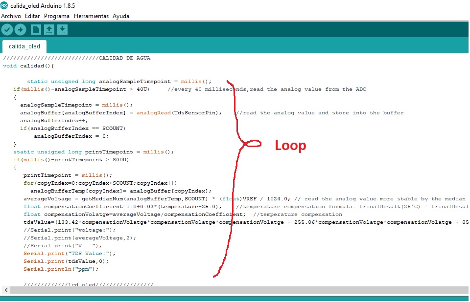
Variable configuration.
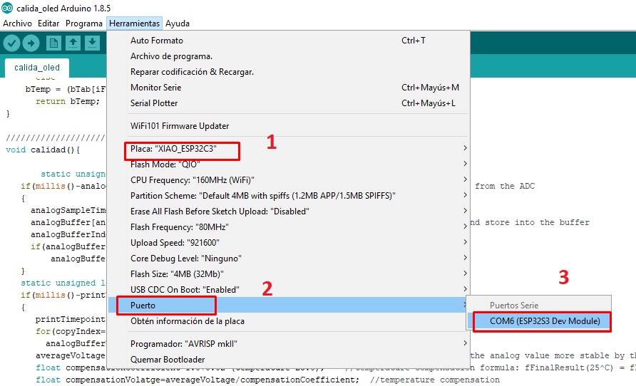
Selection of XIAO ESP32-C3 electronic board.
After compiling the code correctly and checking for errors, we proceed to load the program on the XIAO ESP32-C3.
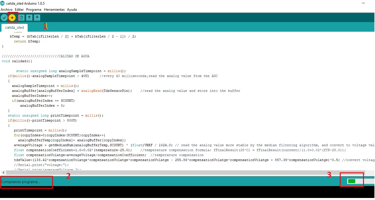
LOADING the program.
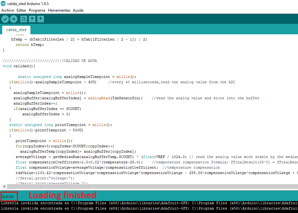
Loading finished.
Finally, we proceed to carry out tests on the developed board, using the same components mentioned above, as can be seen in the following example
Oled LCD and TDS.
Own control board
With great enthusiasm, I carried out the individual assignment, which gave me the opportunity to experiment with the XIAO RP2040 and XIAO ESP32-C3 control boards. I made small examples based on the requirements of my final project, which motivated me to improve this board to achieve a more efficient and compact pin layout. This process allowed me to become more familiar with the XIAOs and design a board that perfectly fit my needs.
Development of custom electronic boards with CNC Router.
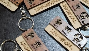
Development of personalized keychains and ornaments with CNC Laser.
Development of custom machines "Desktop CNC Laser.

Huánuco is a Peruvian city, capital of the district, province and department of the same name in the north-central area of the country. The city has a population of 235,529 inhabitants. .